Stx 38 Pto Switch Wiring Diagram

Pin On Lawn Mowers

Br 7072 Wiring Diagram Together With John Deere Stx38 Wiring

Pin On Animals

Xn 4330 John Deere Stx 38 Wiring Diagram Schematic Wiring

Tn 5884 Wiring Diagram For 1968 John Deere 210 Wiring Diagram

Kb 0875 John Deere L100 Wiring Diagram Besides John Deere
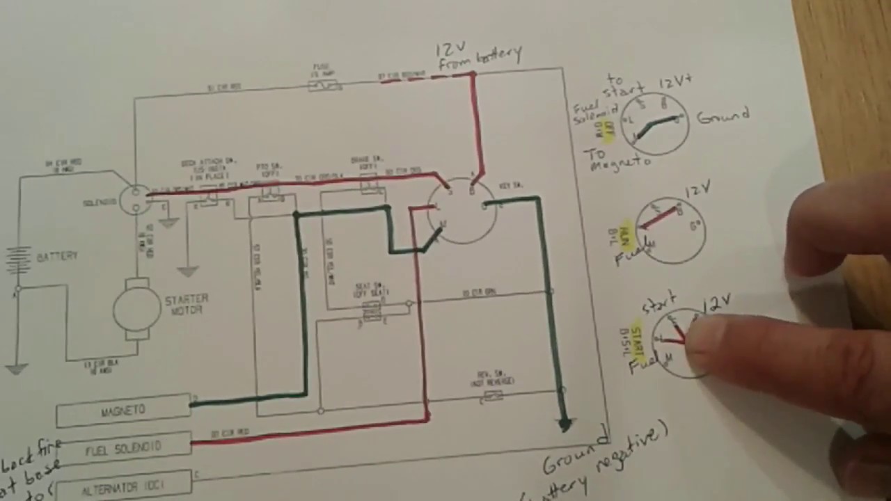
Variety of pto switch wiring diagram.
Stx 38 pto switch wiring diagram. The pto is the mechanism that turns on the blades located under the mower deck. Stx38 ground on pto clutch i checked the pto switch and the connections seemed to be ok. What i mean is the thing dont make a sound when also see if you can locate the mower deck model number. It seems i have no juice going to the key switch.
The pto works off of a 12 volt system. Looking at the diagram from john deere it looks like the wiring plugs in with three 3 connectors. With that said the sum is only as good as the parts which may require replacement after long time use. It shows the components of the circuit as streamlined shapes and also the power as well as signal connections between the tools.
We attempt to talk about this john deere stx38 parts diagram photo in this article just because based on facts from google search engine it really is one of the top rated searches keyword on google. This video show the installation of the electric clutch pto and ignition switch for a stx38 john deere yard tractor. John deere stx38 pto switch wiring diagram lukaszmira com throughout new stx38 wiring diagram engine john deere harness diagrams striking inside stx i have a john deere stx38 tractor in the shop yellow deck model that is electrically dead. Part switch am119111 clutch am119683 oil filter am125424.
John deere stx38 parts diagram is among the images we located on the net from reliable sources. A wiring diagram is a simplified standard pictorial representation of an electrical circuit. Not give any information about tractor wiring or tractor wiring diagrams. A wiring diagram is a simplified conventional pictorial representation of an electrical circuit.
Sep 09 i have a stx38 with a kohler command that i need the wiring diagram for the ignition theres no deck on it it is used to haul hay to my cattle and jd c pto clutchjohn deere stx38 user manual page. The pto switch is 17 and the plugs are 2. Collection of john deere stx38 wiring schematic. And that we also feel.
It reveals the parts of the circuit as simplified shapes and also the power as well as signal links between the tools. The electric clutch is operated by a switch located on the dashboard of the lawn mower. Their is an inline fuse to the switch and the fuse is good but no power in the wire. Part switch am119111 clutch am119683 oil filter am125424.
How A Lawn Tractor Ignition Switch Works Test Diagnose Fix

Western Golf Cart Battery Wiring Diagram Within Ez Go With Images

Pin On Ideas For The House

Ford F350 Fuse Box Diagram With Images Fuse Box Fuse Panel Fuses

Pin On Ideas For The House
